jueves, 26 de julio de 2012

NSX Pikes Peak Special


F22 head

K20a head done and started a new project. F22.
it's a simple design head, straight port, without flow channels.
a speed analysis tells me that there is not too much gain on this head, no bebds to work on, no divider for the valve guide to channel the flow to avoid the divider...etc...  very simple design.
OEM flows 234CFM at max lift..  achieved 251-254CFM. i don't have a spare head to go further on the design, so this numbers were gained on the customer head directly. no trial and error this time.

working on it, the shaft of the grinder broke .


254CFM design. worked on some high speed areas, not too high compared with the previous head i've done, k20A.

F22 intake

jueves, 19 de julio de 2012

k20a exhaust side

done the exhaust side.  330CFM
worked on the high speed areas, flow increases very rapidly with a minor change, but always in the correct areas.  all the dividers are angled towards the centre exit of the port.
the valve guides need a change, but that work is done by the customer.
some work on the chamber and done.


K20A2 apple design

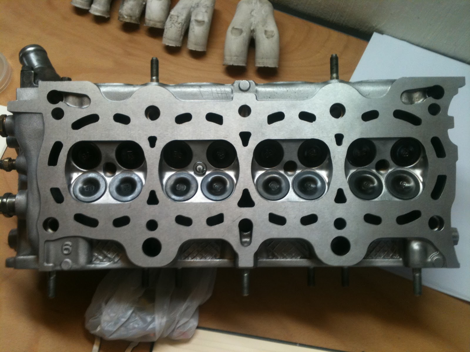
been busy working on a k20A2 head. in a previous post i told that this head breaths from the roof. i was wrong. i checked the flow velocity in differente points , and air tend to flow more from the bottom and centre of the port, arround the divider. at other points, the velocity is almost zero, very curious because i see  other works (without flowbench) on this head and in some cases are very different.

this design is common. only 3 days of work, achieved a maximun of 323CFM at .49" lift. is the first k20a head, so sure i improve this numbers in the next k20a head.
at .49" lift, this head in factory specs flows 284CFM.
I have to say that in factory specs, each port flows different and get different results. it's very difficult in this head  get the same numbers, because without a CNC, it's almost impossible to do 4 ports with the same shape.
40grit finish. other heads i've done, i finished with 80grit, but in my opinion it's too shiny. i like a rough surface, so fuel particles attach easily.


jueves, 12 de julio de 2012

K20a intake manifold proto

devote some time for the k20a intake proto. i modified the bellmouths to have more room in the plenum i
am designing.  the bellmouth outer diameter is 90mm, which i reduced to 72mm in the lathe.


miércoles, 11 de julio de 2012

Finally K20A2

Today started a new head for a guy from barcelona. it's the typeR ep3 head. together with s2000 head, the best head from Honda factory.
i played with the flow balls, seeking which areas flow more. first of all, ports on this head are very angled
from port entry to valve seat, so breaths more from the roof rather than from the floor of the port.
For instance, placing a flow ball in the floor before the divider, flow increases up to 7-9CFM, so the floor must remain untouched.
Around the valve guide, air flows more easily from the wall side,placing again a flow ball in that point, decreases flow much more than doing it in the divider side.
Tomorrow will follow studying this head, in the valve throat and valve seat area.


d16y8 final numbers

planished head(.7mm) and work finished.
checked again flow numbers,at .380 lift and achieved 218CFM in all the ports, with a variation of 2-3CFM.
sent to my customer this afternoon.


lunes, 9 de julio de 2012

D16y8 intake welded

Didn't weld for a long time, but it doesn't look that bad. Need to do it with greater frecuency.

sábado, 7 de julio de 2012

Turbulent vs Laminar Flow. Flow velocity profile

Not all fluids particles travel at the same speed within a pipe. the shape of the velocity curve depends
wether the flow is laminar or turbulent.
If the flow is laminar, the shape is of the curve is parabolical with maximum velocity at the center, which is twice
the velocity of the pipe wall. the velocity of the wall almost is zero.
in turbulent flow, the entire fluid flows at a given velocity, without that parabolic shape, an the velocity is less 
than laminar flow in the same pipe diameter.
see the picture.


personal project

i was involved... no.. someone involved me in a traffic accident(civic beagle) several months ago. my insurance company said that the car was too old(17 years) so they paid me some money and cancel my contract with them. i repaired it a little bit, but without  MOT and without insurance, i parked at the garage until now. i hired a garage in the same building where jaas is based, so i can work on it now.

the plans are to rebuild the engine for a turbo setup, aiming to reach 250cv and 29-30kg of torque.
first of all, i need to  solve the ECU issue. this car has an automatic transmission, which is managed with its own ECU, and this is connected with the engine ECU .
so i am  converting from OBD0 to OBD1 to be able to use a programmble ecu. i plan to use neptune + demon.

a picture of the turbo.


velocity probe

i am going to update my flowbench with a velocity probe.  with this  i am going to be able to measure velocity in fps(feet per second) in any point of the port.  this  allows me to know where the air is travelling faster, best spots to work and where the air wants to flow. remember that the air flows where less resistance to flow is.

more y8 intake

been working on this intake all the day. i recovered only 3.5% of airflow, with port matched throttlebody. i guess i can't get more cfm on this,so i'm going to close and weld it.
despite d16z6 intake  flowed more, the bigger plenum of y8 benefits high rpm or turbo applications. the reason that z6 flowed more,is in its larger runner, about 20mm more.   we calculate flow with the following formula   cfm= velocity * area.  area o a pipe is calculated by  A= D *3.14* L.
diammeter of both pipes are the same, so a larger runner increases the flow, but there is a problem with the inrceased lenght of the runner in case we want to exchange runners each other. the harmonics.
usually we seek the third harmonic which give us more torque, extending the the runner maybe we lose the optimum lenght to use third harmonic. i have to calculate this for a engine reving up to 7500rpm.
a picture of both intakes.

viernes, 6 de julio de 2012

D16Y8 intake manifold flowed

flowed today the intake manifold to see the loss of cfm. in a previous entry i spoke about  this manifold(how good is compared to other D ntakes) and surprisingly lost more cfm than a D16Z6 intake. 3.5% more of airflow loss. maybe the benefit of this intakes resides in the bigger plenum but for turbo applications. need to compare the runners each others. z6 runners are 20mm longer, but with less angle towards the intake port of the head. 

miércoles, 4 de julio de 2012

D16Y8 225CFM !!

last night worked more on a spare D16Y8 cylinder head. developed a new idea, removing less material, playing with flow balls and understanding  where the air wants to flow.
achieved  225CFM at only .380" of valve lift.
now going to planish the head .7mm.

pics of  finished head soon.

kh7+brush

clean and ready to work.

lunes, 2 de julio de 2012

D16Y8 intake manifold

new project for the d16y8 customer.
jaas flowed intake manifold. this intake works far better than the one that is used on other D16 engines.
plenum has more volumen, but runner entry area is more elliptical.


checking for leaks


D16Y8

Almost finished D16Y8 head. Need to buy a grinding stone to reshape and clean the exhaust valve seat angles, check the seal of intake valves and cc the chambers and done.
this cylindder head is going to be raced with OEM camshafts, so the goal was to achieve the maximun flow at low valve lifts. finally, achieved 205CFM at .380" in intake and 182CFM at .3"  in exhaust. Thats an increase in flow of  > 15%, combined with a jaas flowed intake manifold, which is a estimated gain of 6% more of airflow.
Bear in mind that i always mention airflow, but most important is the speed of that airflow, which raises your volumetric efficiency and fills the power(torque) curve between the maximum torque point and maximum rpm.


domingo, 1 de julio de 2012